


PARASET - World War II Spy Transceiver
The Paraset was a three tube transceiver developed by the British during the early part of World War II. It was a "Spy Radio" used by the resistance forces on the mainland of Europe. Messages were sent on schedule from an array of powerful transmitters in Britain and the Parasets replied.
The complete transceiver, including a built-in key, was contained in a metal case about the size of a large Kleenex box. It was easy to store and hide and move quickly if necessary. Only a few feet of antenna wire was required. The Paraset operated from a separate six volt vibrator supply, so a car battery could power it. It used a 6V6 as a crystal controlled oscillator/transmitter with an output of 4 to 7 Watts. The regenerative receiver consisted of two 6SK7s. The receiver was very sensitive, but not very selective. A two-position range switch allowed continuous operation between 3.3 and 7.6 Megacycles.
I’d been looking for just the right project to build using tube technology. I was just a kid during WWII, and played "War" with the other kids on our block. Especially after seeing a movie showing secret agents operating behind the lines, we would all be secret agents for a week. The Paraset would have been our ideal radio. Since it’s small, QRP power and size, and operates on two of the current ham bands, it seemed ideal for my glow bug project.
The Paraset is described in some detail in a book, "Secret Warfare" adapted by David Kahn, who translated it from the original French book, written by Pierre Lorrain. This book, ISBN 0-85613-586-0, covers much of the equipment used in the clandestine warfare of WWII, including a section on the various secret code systems used.
The Paraset Replicas originated with a Belgian ham, ON5LJ, who apparently found one in a museum and researched the circuit, made drawings, etc. His work was discovered by Mario, IK0MOZ, who, along with his friends, made several replicas from drawings furnished by Jo, ON9CFJ. Mario documented their work on his web site. He includes circuit diagrams. This information was all I needed to get started with my own Paraset replica.
The URL is: http://www.qsl.net/ik0moz/paraset_eng.htm
The pictures below show the Paraset in various stages of construction. Several Knightlites have started construction of their own Parasets so before long we hope to have an all-Paraset roundtable QSO.
Paraset Construction hints:
I found most of the parts at Dayton last year. They are all available with some searching.
The Case:
Building the case is an interesting problem. It has to be fashioned pretty much by hand if you want to build a real replica. The originals were made of steel, and mine is made from the tops of a couple of old VCR cases. The top and bottom pieces were bent first, into a "U" shape. Then, the end pieces were bent with tabs fitting inside of the "U"s. I used an aluminum chassis which just fit inside the bottom.
This is the> case as it was constructed from sheet steel. Regular galvanized steel, about 20 guage, was used for the end pieces and for the ½" strip around the top edge. This strip becomes the lip that overlaps the bottom of the case.
I cleaned (sanded) the joint between the ends and the top and used an old, heavy, 250 watt soldering iron to make the joints. Soldering is tedious, and should be done starting at the center of a seam, working toward the end or edge. If you start at one end and work toward the other, the two pieces of metal will expand at different rates, resulting in gaps or corners which don’t seem to match. However it’s done, this problem of differential expansion should be considered and made to work for you instead of against you.
After the top and bottom shells were complete, I cut a ½" strip of metal and soldered it around the open edge of the top, forming the lip which overlaps the bottom of the case.
Small gaps in the solder and other deficiencies can be repaired with automobile body putty before the final painting. Mine is painted with Krylon NO. 1606 Pewter Gray Gloss, which is very close to some of the original WWII colors.
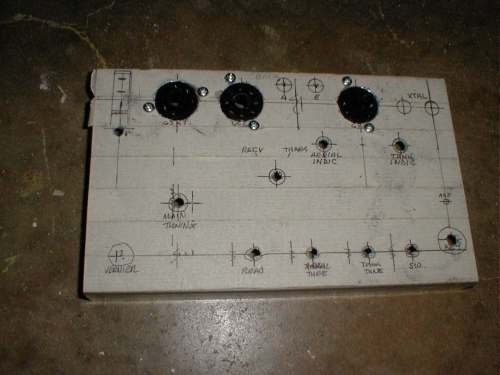
This is the aluminum chassis, covered with masking tape and marked for the various holes. The tube sockets have been mounted.
Small Parts:
Most of the internal small parts can be obtained by robbing them from an old tube-type radio. I deviated from the "authentic" a little bit on the internals. I used some silver micas and other caps that were not vintage. The original used wafer tube sockets, but I used Bakelite sockets.
The hardest part to find is the 36 henry choke. I'm told that anything above about 18 henrys will work. I used a large (too large) 30 henry choke that was all I could find. Didn't have a good way to measure such a large inductance, but I think the primary of an old tube type output transformer would work, since the current drain is very low.
Other parts that were hard to figure out were:
1. The power plug. This turned out to be standard three pin Cinch-Jones connectors. (the original used a female plug on the chassis and a male plug on the cord. For safety reasons, most of the replicas reverse this. I didn’t)
2. The crystal jack was 3/4" spacing for large pins. I found three jacks at Dayton, bought them all, along with some crystals, and when I got home, I discovered that two of the jacks were for slightly smaller pins than the vintage crystals.
3. Be aware that there are three 100 mmfd variables and one of them must have an insulated frame.
4. The aerial and earth jacks are simply banana jacks.
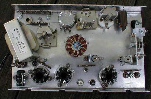
The underside of the chassis ready for wiring, with all of the hardware mounted. Note the choke which is twice the size of the original. The rotary wafer switch in the middle was later replaced by a smaller rotary DPDT.
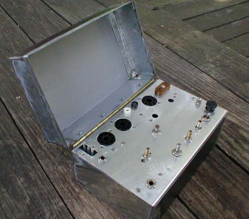
The unfinished case and chassis fitted together before wiring and painting.
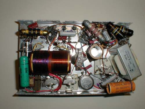
Wiring completed. There are two or three layers of parts in some places. Note a mixture of vintage and modern capacitors and resistors were used in the interest of conserving space.
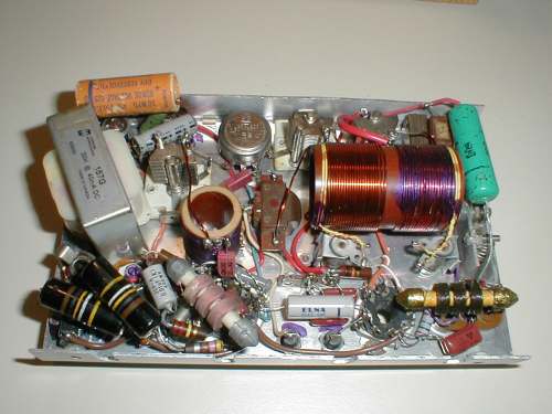
The wired chassis from another viewpoint. Note the yellow two turn coils at each end of the main coil. These are pick up loops for the tuning indicators. During final testing these loops were reduced to one turn each to keep from burning out the indicator bulbs.
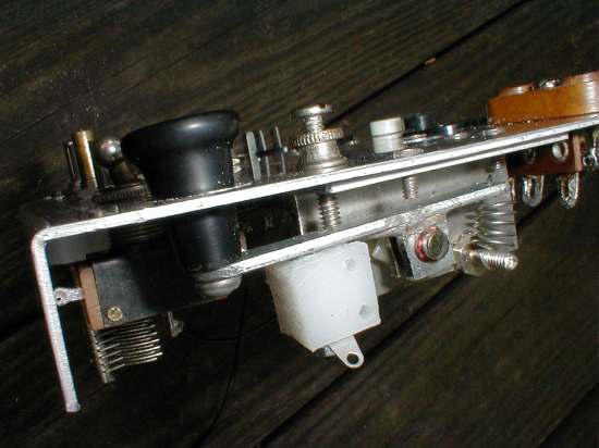
This end view of the chassis shows the hand made key mechanism. It’s a simple lever with spring tension at one end and a screw adjustment on top of the chassis. The contacts are between the plastic block and the lever. The knob protrudes from the lever through the top of the chassis. The smaller screw holds the key in place.
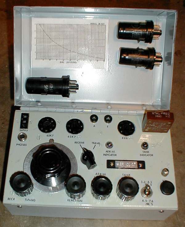
The completed Paraset as it appears when the case is opened. Note the tubes are stored in clips inside the lid. The chart converts the 0 to100 dial readings to megacycles.