Telescope mounted KA7OEI Optical Receiver
The following describes an optical communications receiver
project initiated by a small group of Knights inspired by one of
our most recent members (Sir Rye, K9LCJ). As a result, we can now
proclaim that we're involved in everything from DC to light.
Sir Rye provided a demonstration of his LED communications system when
we were first introduced at our August, 2008 QRPigOut. He
described some of the work and communications achievements that
have been published. He described how he was inspired by a group of
hams in Tasmania and then provided his choice list of websites to
visit, and we were suddenly swept off toward another fun and
challenging adventure.
Sir Rye provided the following list of reference url's which I'm
posting here as must review sites since they continue to provide much
useful and valuable insight and guidance for us. In Sir Rye's own words:
There
are about five pivotal web sites for this optical/LED comms
stuff:
The
Radio and Electronics Club of
Southern Tasmania is the most interesting and their activities are quite
well documented. This site takes days to wade through.
Clint
KA7AOI holds the US (world??) record for LED comms of 173 miles. The
linked page has a couple of interesting pictures. One shows a LED emitter from
14 miles and there are a couple of comparison pictures of LED versus LASER
signals showing the fading characteristics of each. There are links to a
bunch of good things at the bottom of this page including Understanding
the Performance of Free Space Optics, Decibels
versus Dollar that I mentioned last night (presented by the VK7s), and a
whole bunch of other really interesting stuff. Clint seems to be another of the
hyperactive hams to which we all aspire.
F1AVY Yves has a
really nice web presence, but it’s a little hard to navigate. It appears as if
he has been messing around with this stuff for a long time and has a good
background in optics etc. His focus seems to be more on LASERs. He has a good
presentation on Cloud
Bounce as well as a lot of other activities centered on optical comms. The
graphs of path loss are quite exciting.
W1VLF did (does??)
some interesting cloud bounce stuff using massive arrays of smallish IR LEDs.
I think this was all before the advent of the big visible light LUXEON diodes.
Alberto I1PHD is the author of the
SPECTRAN software that I demonstrated last night. He’s another one of those
fine guys who can’t seem to stop producing really good technical tools for us
Hams.
There
are links on these pages that reach out to almost everything else on the topic.
It is interesting to note that most of this work is being done overseas. I was
glad to find the KnightLites as you guys seem to be one of the last bastions of
Ham homebrew in the area. The TAR robotics guys also seem to be into soldering
iron burns…
It wasn't long before we realized that this was a convergence of our
shared interests in QRP, and amateur astronomy, and the hook was set.
As we shared ideas and insights, we discovered that we shared other
interests as well... such as circuit board building processes. That led
us to a recent revelation that Staples makes the best darn paper a PC
board maker would ever want. The story is long to be told, but the path
to where we are today has been fast and furious, and that brings this
discussion to where my story begins.
I am easily inspired by the enthusiasm and excitement of others, and
can't resist getting myself involved. That was the lure that drew me
into this project. Sir Chris (KD4PBJ) first met Sir Rye at the Cary hamfest in July,
and learned that he was in search of a group of spirited hams that
still liked construction projects. Sir Chris instantly recognized that
he was one of us, and wasted no time inviting him to join us at our August
QRPigOut. In the meantime; he was becoming intensely integrated in the
work that Sir Rye was doing, and enthusiastically sharing his insight
with me. Again the story becomes long, but soon I was learning about
high power LEDs, optical communications systems, experiments, and
communications link records. That quickly led to my own pursuit of a
system, and with a slight nudge from Sir Rye, I found myself gathering
parts for a system of my own. Having not yet acquired any optical
hardware, I suggested that I use my telescope for the task, and decided
to start with a receiver. After a brief period of brainstorming and
digging through my junque... or rather "jewel" boxes, I discovered that
a copper plumbing coupler was a perfect fit into the eyepiece holder of
my telescope, and the idea of an optical eyepiece was born.
Once again, with Sir Rye's enthusiastic influence, I was introduced to Cadsoft's EAGLE Light
Freeware PCB layout software. I learned that Sir Bob (AE4IC) was
already consumed in using it, and also on track toward building an
optical system as well. Sir Bob encouraged me to give it a try, and
that the learning curve would go quickly. Indeed; all that was being
shared was just as advertised. Within a day I had one of KA7OEI's
optical receiver schematic entered, and was manipulating the
parts placement on the board. Within 3 days, I had the layout completed
and I was ready to etch a board.
Oh yes... Did I fail to mention that we needed to somehow get that nice
EAGLE Light file onto a circuit board? Well... That's another fun part
of this project... That story is long as well, and all the important
details can be found at:
We (Sirs, Chris, Rye, Bob, and myself) took nothing at face value, and
its in none of our personalities to delegate such matters as proving a
concept or that a process works as advertised, so we all set off
independently to pursue improving the process. We all failed miserably
on that agenda, but much to our delight, we all came to the same crisp
conclusion that the process is well polished, is easy to reproduce, and
is cheap and efficient. We even compared two different etchants, and
found both equally safe to work with, and easy to use.
Our conclusions on the board photo resist process we investigated and
now unanimously endorse are once again best summarized in Sir Rye's own
words:
Upon looking at Tom Goottee’s web page
(which is where this all started) I find that it has everything you need to know
about the process in well written detail. In many respects we just reinvented
the wheel, but it was a good proof of concept effort.
About the only thing that I have found that probably isn't
emphasized enough on Gootee’s page is that you have to use a good copier. Some
of the smaller office type machines don’t give good results. Staples, Office
Depot, and Office Max all have big Xerox copiers that do a good job of laying
down toner.
Gootee emphasizes that “it’s the paper” and I believe
we have proved that again. Use the Staples Paper unless you want to waste a lot
of time before you finally go to Staples and get the right stuff….
Staples
Photo
Basic Gloss
for Inkjet printers Item #648181
Accept no substitutes!
The etchants we compared and agree are equally safe, cheap and effective are:
Ferric Chloride
&
Muriatic Acid and Hydrogen Peroxide:
Its important to note that obtaining Ferric Chloride may be a tad more
difficult, and should probably make it your second choice if you're
just starting to consider producing your own high quality printed
circuit boards.
The history and technical details for the KA7OEI optical receiver I adopted for this project can be
found at the following urls:
The receiver shown in the following photographs is an electrical
clone of the Simplified Version of KA7OEI's "Version 3" Optical
Receiver. I abandoned his reverse voltage power protection scheme in
favor of my own less sophisticated approach however, by eliminating his
shunt diode (D1) and series self-resetting thermal fuse (TH1), and
inserting a series connected 1N4148 diode (anode to battery
positive terminal) to achieve the intended result.
I also substituted an MPF-102 on the front-end in lieu of the 2N5457
identified in his schematic, and 2N3904's for both of his MPSA18
NPN transistors. I also used 47 uF for all of the electrolytic bypass
capacitors throughout with the exception of C4. I actually used a much
larger value of 100 uF for C4 whereas this is much smaller (2.2 uF) in
his schematic. I would have to say that changing C4's value so
dramatically is the most significant deviation I made from his
published design, but it hasn't surfaced as an issue so far, and
I'm aware of this difference if I discover an elusive anamoly down the
road. Since this serves as a DC bias current
bypass, I suspect the impact is principally
excessive dampening of the DC bias response time due to large
changes in signal interference levels.
I entered the schematic into the free version of the EAGLE PCB layout
program, and designed a board which would allow me to insert as an
"eyepiece" into my telescope with the detector diode optimally
centered and positioned at the focal point of the primary lens.
The schematic shown here is what I produced in EAGLE Light:
... and the EAGLE layout editor enabled me to effortlessly design the following PC board layout:
WARNING!
This schematic (and layout) shown here are both in error (the
inputs of IC1A are reverse connected). Refer to KA7OEI's schematic instead...
at least until this disclaimer is removed. Its an easy cut and jumper
fix if you leaped into this with exuberance and anxious enthusiasm
before reading this, but it just won't look quite as pretty.
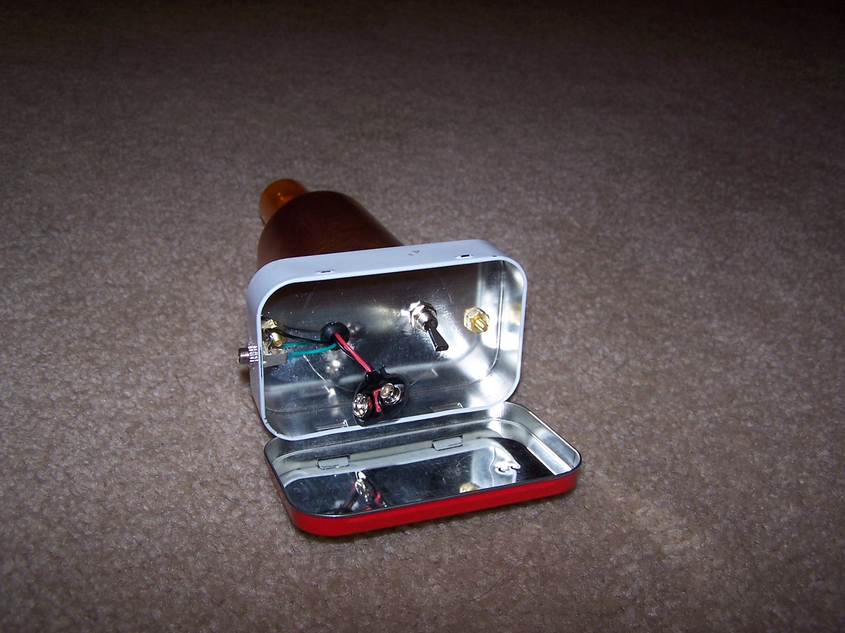
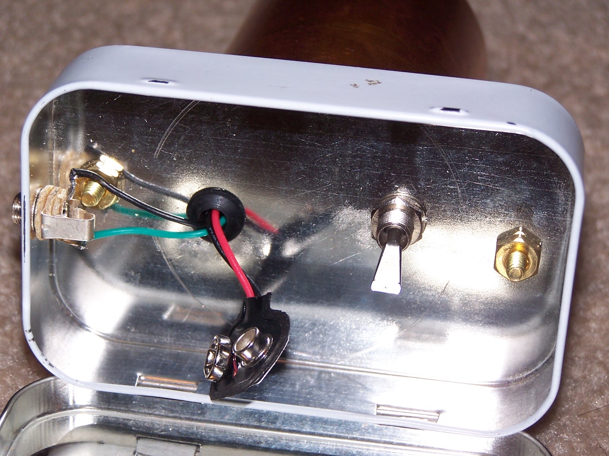
The following is a photo of the inside of the Altoids tin used to
house the 9V battery, The lid serves to contain the battery and doubles
as an additional EMI shield to protect the otherwise exposed power and
output signal wiring.
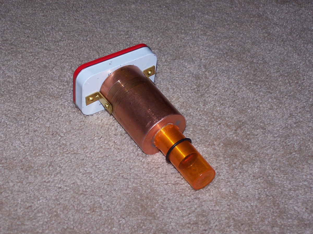
The following shows the completed receiver assembly with its lens cover
fashioned from a pill bottle. The pill bottle has a slot cut into one
side that enables the o-ring shown to function as a keeper that
prevents the lens cover from falling off easily. The circuit board is
completely housed and mounted inside the dual diameter copper coaxial
assembly, with the narrow end inserted into the smaller coaxial
section that was fashioned from a standard 3/4 inch copper tubing
coupler used in house plumbing applications. The O.D. of the coupler
serendipitously matches the standardized 0.96" eyepiece diameter,
making it a perfect match for this receiver.
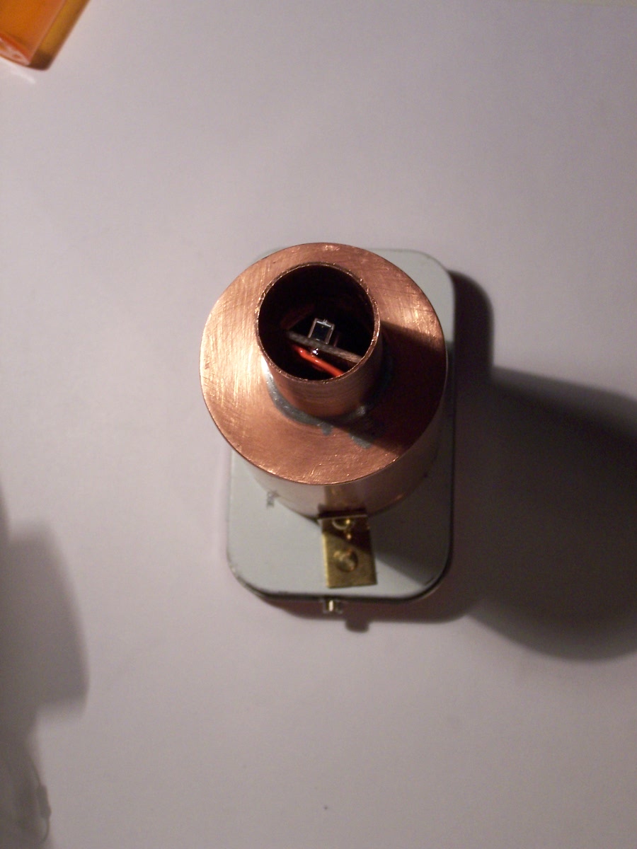
The following reveals the "business end" of the receiver assembly which
becomes the "lens" that gets inserted in the eyepiece holder of the
telescope. Thankfully, the detector diode is easily seen in this photo.
I was reluctant to use my flash for this view out of fear of damaging
the detector. I wasn't going to take that risk for a photo shoot, and
I'm glad the results without a flash came out so well.
The following photo shows where the receiver interfaces with
the outside world. There are several noteworthy points to observe
in this photograph that are obvious, but perhaps not immediately
apparent:
1. The gain control switch is mounted such that its
wiring remains inside and never exits the coaxial receiver chamber.
2. The gain control switch is installed within and
thus shielded by the Altoids tin when the lid is closed.
3. The battery used to power the receiver is
contained within (and under the cover) the Altoids tin when operating.
4. 4 wires (battery +, battery -, Audio, and ground)
enter/exit the receiver through a single 1/4 inch hole in the bottom of
the Altoids tin.
The boundary between the receiver and the outside world provided
by maximizing the integrity of the Altoids bottom, compartmentalizing
the power system, and minimizing the lead lengths of
the essential power and signal output leads entering/exiting
the coaxial receiver chamber, results in a receiver that is nearly
perfectly immune to EMI.
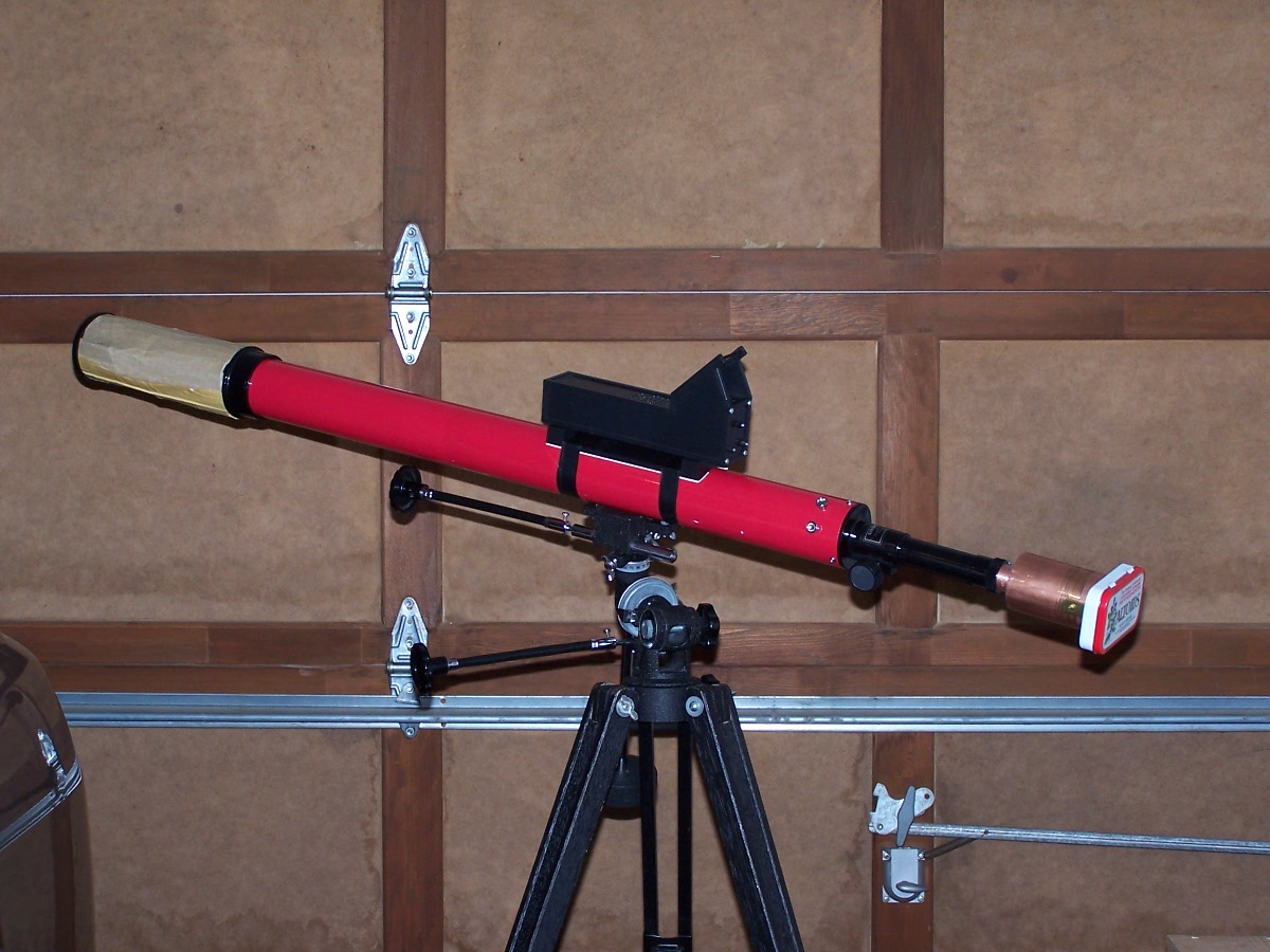
The following shows where one might find light at the end of the tunnel.
The finished telescope mountable version of KA7OEI's optical receiver is now mounted and ready for service.